This guide is intended to give a brief introduction to the world of emulation and will also teach you how to write one yourself from scratch.
Personally I have been excited about emulators since the late 90’s. As I didn’t own a console back in the days (our family only had a C64), I was pleasantly surprised when I learned that you could use an emulator to run console games on the PC. I still remember playing Super Mario 3 on the PC using a SNES/Super Famicom emulator Snes9x and a few years later completing Metal Gear Solid using Bleem! (a PSX emulator).
These days however I’m more focussed on providing support to emulator projects of recent consoles such as: PCSX2 (Sony Playstation 2), Dolphin-emu (Nintendo Gamecube and Wii) and nullDC (Sega Dreamcast).
While this guide expects you to have some basic knowledge of computer systems and assumes you know a program language, it should also be an interesting read for people who are interested in emulation in general.
#define emulator
I think it’s important to first understand what an emulator is and isn’t.
An emulator is a computer program that mimics the internal design and functionality of a computer system (System A). It allows users to run software designed for this specific system (Sytem A) on a totally different computer system or architecture (System B).
Often people confuse a simulator with an emulator and vice versa. Just remember that these words aren’t synonyms.
Let’s take a look at the following example:
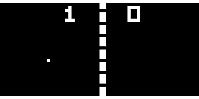
Pong is a 2D tennis game which was developed by Atari and ran on their own hardware. However, the game wasn’t just available on Atari systems, but also on rival platforms such as Amstrad, Amiga and the C64.
Since not every Pong game was licensed by Atari to run on these platforms, it also meant that not every game was running the code from Atari. Basically what happened is that people created their own implementation (clones) of the game Pong. In this case they simulated the looks and game behavior of Pong.
In case of an emulator, we choose not to re-implement the game Pong for our native system. Instead, we re-create the environment with a computer program which allows us to run the original machine code of Pong. A benefit of this is that it won’t just allow us to run Pong, but also any other application developed for that platform.
What is a CHIP-8?
The Chip 8 actually never was a real system, but more like a virtual machine (VM) developed in the 70’s by Joseph Weisbecker. Games written in the Chip 8 language could easily run on systems that had a Chip 8 interpreter.
Why start with a CHIP-8 emulator?
Writing a Chip 8 emulator is probably the easiest emulation project you can undertake. Due to small number of opcodes (35 in total for Chip 8) and the fact that a lot of instructions are used in more advanced CPUs, a project like this is educational (get a better understanding of how the CPU works and how machine code is executed), manageable (small number of opcodes to implement) and not too time consuming (project can be finished in a few days).
Before you start…
- Pick a programming language you’re familiar with (C/C++ or Java are common). The examples below will use C/C++
- Don’t use this project as a way to learn how to program. (If bitwise operations confuse you, study them first)
- You will probably need to use 3rd party libraries to handle audio / video output and user input (GLUT / SDL / DirectX)
- OK GO!

CPU Specifications
When you start writing an emulator, it is important that you find as much information as possible about the system you want to emulate. Try to find out how much memory and registers are used in the system, what architecture it is using and see if you can get hold of technical documents that describe the instruction set.
In the case of the Chip 8, I would recommend taking a look at the Chip 8 description on Wikipedia.
I’ll give you a brief overview of the Chip 8 system and some hints on how to implement the essential parts:
- The Chip 8 has 35 opcodes which are all two bytes long. To store the current opcode, we need a data type that allows us to store two bytes. An unsigned short has the length of two bytes and therefor fits our needs:
unsigned short opcode; - The Chip 8 has 4K memory in total, which we can emulated as:
unsigned char memory[4096]; - CPU registers: The Chip 8 has 15 8-bit general purpose registers named V0,V1 up to VE. The 16th register is used for the ‘carry flag’. Eight bits is one byte so we can use an unsigned char for this purpose:
unsigned char V[16]; - There is an Index register I and a program counter (pc) which can have a value from
0x000to0xFFFunsigned short I; unsigned short pc; - The systems memory map:
0x000-0x1FF - Chip 8 interpreter (contains font set in emu) 0x050-0x0A0 - Used for the built in 4x5 pixel font set (0-F) 0x200-0xFFF - Program ROM and work RAM - The graphics system: The chip 8 has one instruction that draws sprite to the screen. Drawing is done in XOR mode and if a pixel is turned off as a result of drawing, the VF register is set. This is used for collision detection.
- The graphics of the Chip 8 are black and white and the screen has a total of 2048 pixels (64 x 32). This can easily be implemented using an array that hold the pixel state (1 or 0):
unsigned char gfx[64 * 32]; - Interupts and hardware registers. The Chip 8 has none, but there are two timer registers that count at 60 Hz. When set above zero they will count down to zero.
unsigned char delay_timer; unsigned char sound_timer; - The system’s buzzer sounds whenever the sound timer reaches zero.
It is important to know that the Chip 8 instruction set has opcodes that allow the program to jump to a certain address or call a subroutine. While the specification doesn’t mention a stack, you will need to implement one as part of the interpreter yourself. The stack is used to remember the current location before a jump is performed. So anytime you perform a jump or call a subroutine, store the program counter in the stack before proceeding. The system has 16 levels of stack and in order to remember which level of the stack is used, you need to implement a stack pointer (sp).
unsigned short stack[16];
unsigned short sp;
Finally, the Chip 8 has a HEX based keypad (0x0-0xF), you can use an array to store the current state of the key.
unsigned char key[16];
Game Loop
To give you an idea on how to design your emulator, I made a small example of a layout. It does not teach you how to use GLUT or SDL to handle graphics and input but merely shows you how the flow of your emulator should be.
 1. #include
 2. #include   // OpenGL graphics and input
 3. #include "chip8.h" // Your cpu core implementation
 4.
 5. chip8 myChip8;
 6.
 7. int main(int argc, char **argv)
 8. {
 9.   // Set up render system and register input callbacks
10.   setupGraphics();
11.   setupInput();
12.
13.   // Initialize the Chip8 system and load the game into the memory
14.   myChip8.initialize();
15.   myChip8.loadGame("pong");
16.
17.   // Emulation loop
18.   for(;;)
19.   {
20.     // Emulate one cycle
21.     myChip8.emulateCycle();
22.
23.     // If the draw flag is set, update the screen
24.     if(myChip8.drawFlag)
25.       drawGraphics();
26.
27.     // Store key press state (Press and Release)
28.     myChip8.setKeys();
29.   }
30.
31.   return 0;
32. }
- Line 3-5: In this example we assume you will create a separate class to handle the opcodes.
- Line 10-11: Setup the graphics (window size, display mode, etc) and input system (bind callbacks)
- Line 14: Clear the memory, registers and screen
- Line 15: Copy the program into the memory
- Line 21: Emulate one cycle of the system
- Line 24: Because the system does not draw every cycle, we should set a draw flag when we need to update our screen. Only two opcodes should set this flag:
0x00E0– Clears the screen0xDXYN– Draws a sprite on the screen
- Line 28: If we press or release a key, we should store this state in the part that emulates the keypad
Emulation cycle
Next we will look into the emulation cycle.
void chip8::initialize()
{
  // Initialize registers and memory once
}

void chip8::emulateCycle()
{
  // Fetch Opcode
  // Decode Opcode
  // Execute Opcode

  // Update timers
}
Every cycle, the method emulateCycle is called which emulates one cycle of the Chip 8 CPU. During this cycle, the emulator will Fetch, Decode and Execute one opcode.
Fetch opcode
During this step, the system will fetch one opcode from the memory at the location specified by the program counter (pc). In our Chip 8 emulator, data is stored in an array in which each address contains one byte. As one opcode is 2 bytes long, we will need to fetch two successive bytes and merge them to get the actual opcode.
To demonstrate how this works we will be using opcode 0xA2F0.
// Assume the following:
memory[pc]     == 0xA2
memory[pc + 1] == 0xF0
In order to merge both bytes and store them in an unsigned short (2 bytes datatype) we will use the bitwise OR operation:
opcode = memory[pc] << 8 | memory[pc + 1];
So what did actually happen?
First we shifted 0xA2 left 8 bits, which adds 8 zeros.
0xA2       0xA2 << 8 = 0xA200   HEX
10100010   1010001000000000     BIN
Next we use the bitwise OR operation to merge them:
1010001000000000 | // 0xA200
        11110000 = // 0xF0 (0x00F0)
------------------
1010001011110000   // 0xA2F0
Decode opcode As we have stored our current opcode, we need to decode the opcode and check the opcode table to see what it means. We will continue with the same opcode:
0xA2F0 // Assembly: mvi 2F0h
If we take a look at the opcode table, it tells us the following:
ANNN: Sets I to the address NNN
We will need to set index register I to the value of NNN (0x2F0).
Execute opcode
Now that we know what to do with the opcode, we can execute the opcode in our emulator. For our example instruction 0xA2F0 it means that we need to store the value 0x2F0 into index register I. As only 12 bits are containing the value we need to store, we use a bitwise AND operator (&) to get rid of the first four bits (nibble):
1010001011110000 & // 0xA2F0 (opcode)
0000111111111111 = // 0x0FFF
------------------
0000001011110000   // 0x02F0 (0x2F0)
Resulting code:
I = opcode & 0x0FFF;
pc += 2;
Because every instruction is 2 bytes long, we need to increment the program counter by two after every executed opcode. This is true unless you jump to a certain address in the memory or if you call a subroutine (in which case you need to store the program counter in the stack). If the next opcode should be skipped, increase the program counter by four.
Timers
Besides executing opcodes, the Chip 8 also has two timers you will need to implement. As mentioned above, both timers (delay timer and sound timer) count down to zero if they have been set to a value larger than zero. Since these timers count down at 60 Hz, you might want to implement something that slows down your emulation cycle (Execute 60 opcodes in one second).
Getting started
Now that you know the basics of emulation and how the system works, it is time to put all pieces together and start coding the emulator.
Initialize system
Before running the first emulation cycle, you will need to prepare your system state. Start clearing the memory and resetting the registers to zero. While the Chip 8 doesn’t really have a BIOS or firmware, it does have a basic fontset stored in the memory. This fontset should be loaded in memory location 0x50 == 80 and onwards. More details about how the fontset works can be found at the end of this guide.
Another important thing to remember is that the system expects the application to be loaded at memory location 0x200. This means that your program counter should also be set to this location.
void chip8::initialize()
{
  pc     = 0x200;  // Program counter starts at 0x200
  opcode = 0;      // Reset current opcode
  I      = 0;      // Reset index register
  sp     = 0;      // Reset stack pointer

  // Clear display
  // Clear stack
  // Clear registers V0-VF
  // Clear memory

  // Load fontset
  for(int i = 0; i < 80; ++i)
    memory[i] = chip8_fontset[i];

  // Reset timers
}
Loading the program into the memory
After you have initialized the emulator, load the program into the memory (use fopen in binary mode) and start filling the memory at location: 0x200 == 512.
for(int i = 0; i < bufferSize; ++i)
  memory[i + 512] = buffer[i];
Start the emulation Our system is now ready to execute its first opcode. As mentioned above, we should fetch, decode and execute the opcode. In this example we start by reading the first 4 bits of the current opcode to find out what the opcode is and what the emulator needs to do:
void chip8::emulateCycle()
{
  // Fetch opcode
  opcode = memory[pc] << 8 | memory[pc + 1];

  // Decode opcode
  switch(opcode & 0xF000)
  {
    // Some opcodes //

    case 0xA000: // ANNN: Sets I to the address NNN
      // Execute opcode
      I = opcode & 0x0FFF;
      pc += 2;
    break;

    // More opcodes //

    default:
      printf ("Unknown opcode: 0x%X\n", opcode);
  }

  // Update timers
  if(delay_timer > 0)
    --delay_timer;

  if(sound_timer > 0)
  {
    if(sound_timer == 1)
      printf("BEEP!\n");
    --sound_timer;
  }
}
In some cases we can not rely solely on the first four bits to see what the opcode means. For example, 0x00E0 and 0x00EE both start with 0x0. In this case we add an additional switch and compare the last four bits:
// Decode opcode
switch(opcode & 0xF000)
{
  case 0x0000:
    switch(opcode & 0x000F)
    {
      case 0x0000: // 0x00E0: Clears the screen
        // Execute opcode
      break;

      case 0x000E: // 0x00EE: Returns from subroutine
        // Execute opcode
      break;

      default:
        printf ("Unknown opcode [0x0000]: 0x%X\n", opcode);
    }
  break;

  // more opcodes //
}
Opcode examples
Lets take a look at some more opcodes that might look daunting at first.
Example 1: Opcode 0x2NNN
This opcode calls the subroutine at address NNN. Because we will need to temporary jump to address NNN, it means that we should store the current address of the program counter in the stack. After storing the value of the program counter in the stack, increase the stack pointer to prevent overwriting the current stack. Now that we have stored the program counter, we can set it to the address NNN. Remember, because we’re calling a subroutine at a specific address, you should not increase the program counter by two.
case 0x2000:
  stack[sp] = pc;
  ++sp;
  pc = opcode & 0x0FFF;
break;
Example 2: Opcode 0x8XY4
This opcode adds the value of VY to VX. Register VF is set to 1 when there is a carry and set to 0 when there isn’t. Because the register can only store values from 0 to 255 (8 bit value), it means that if the sum of VX and VY is larger than 255, it can’t be stored in the register (or actually it starts counting from 0 again). If the sum of VX and VY is larger than 255, we use the carry flag to let the system know that the total sum of both values was indeed larger than 255. Don’t forget to increment the program counter by two after executing the opcode.
case 0x0004:
  if(V[(opcode & 0x00F0) >> 4] > (0xFF - V[(opcode & 0x0F00) >> 8]))
    V[0xF] = 1; // carry
  else
    V[0xF] = 0;
  V[(opcode & 0x0F00) >> 8] += V[(opcode & 0x00F0) >> 4];
  pc += 2;
break;
Example 3: Opcode 0xFX33
Stores the Binary-coded decimal representation of VX at the addresses I, I plus 1, and I plus 2 I have to confess that I couldn’t to figure out how to implement this opcode, so I used TJA’s solution.
case 0x0033:
  memory[I]     = V[(opcode & 0x0F00) >> 8] / 100;
  memory[I + 1] = (V[(opcode & 0x0F00) >> 8] / 10) % 10;
  memory[I + 2] = (V[(opcode & 0x0F00) >> 8] % 100) % 10;
  pc += 2;
break;
Handling graphics and input
Drawing pixels
The opcode responsible for drawing to our display is 0xDXYN. The Wikipedia description tells us the following:
- Draws a sprite at coordinate (VX, VY) that has a width of 8 pixels and a height of N pixels. Each row of 8 pixels is read as bit-coded starting from memory location I; I value doesn’t change after the execution of this instruction. As described above, VF is set to 1 if any screen pixels are flipped from set to unset when the sprite is drawn, and to 0 if that doesn’t happen.
As the description of the opcode is telling us, the Chip 8 actually draws on the screen by drawing sprites. It will give us the location of where the sprite needs to be drawn (the opcode tells us which V register we need to check to fetch the X and Y coordinates) and the number of rows (N). The width of each sprite is fixed (8 bits / 1 byte). The state of each pixel is set by using a bitwise XOR operation. This means that it will compare the current pixel state with the current value in the memory. If the current value is different from the value in the memory, the bit value will be 1. If both values match, the bit value will be 0.
01000101 ^
11110011 =
----------
10110110
Lets assume it the opcode was 0xD003. This means it wants to draw a sprite at location 0,0 which is 3 rows high. At memory location I, the following values were set:
memory[I]     = 0x3C;
memory[I + 1] = 0xC3;
memory[I + 2] = 0xFF;
How do these 3 bytes represent a sprite? Take a look at the binary values of each byte:
HEX    BIN        Sprite
0x3C   00111100     ****
0xC3   11000011   **    **
0xFF   11111111   ********
You should use the binary representation to fill your array (gfx[]). However, before setting the value in gfx[] using the XOR operator, you will also need to check if any of the pixels changed from 1 to 0. If this is the case, you should set the VF register to 1 (This is basically a test for collision detection).
Example of the implementation of opcode 0xDXYN
 1. case 0xD000:
 2. {
 3.   unsigned short x = V[(opcode & 0x0F00) >> 8];
 4.   unsigned short y = V[(opcode & 0x00F0) >> 4];
 5.   unsigned short height = opcode & 0x000F;
 6.   unsigned short pixel;
 7.
 8.   V[0xF] = 0;
 9.   for (int yline = 0; yline < height; yline++)
10.   {
11.     pixel = memory[I + yline];
12.     for(int xline = 0; xline < 8; xline++)
13.     {
14.       if((pixel & (0x80 >> xline)) != 0)
15.       {
16.         if(gfx[(x + xline + ((y + yline) * 64))] == 1)
17.           V[0xF] = 1;
18.         gfx[x + xline + ((y + yline) * 64)] ^= 1;
19.       }
20.     }
21.   }
22.
23.   drawFlag = true;
24.   pc += 2;
25. }
26. break;
- Line 3-4: Fetch the position and height of the sprite
- Line 5: Pixel value
- Line 8: Reset register VF
- Line 9: Loop over each row
- Line 11: Fetch the pixel value from the memory starting at location I
- Line 12: Loop over 8 bits of one row
- Line 14: Check if the current evaluated pixel is set to 1 (note that
0x80 >> xlinescan through the byte, one bit at the time) - Line 16-17: Check if the pixel on the display is set to 1. If it is set, we need to register the collision by setting the VF register
- Line 18: Set the pixel value by using XOR
- Line 23: We changed our
gfx[]array and thus need to update the screen. - Line 24: Update the program counter to move to the next opcode
Input
The Chip 8 system uses a simple HEX keypad that allows users to interact with the system. For our emulator this means we need to implement a method that will set the state of each key in the variable that handles the key states. Every cycle you should check the key input state and store it in key[].
It actually doesn’t matter what value you store, because opcode 0xEX9E and 0xEXA1 only check if a certain key is pressed or isn’t pressed. Opcode 0xFX0A only waits for a key press, and when it receives one, it stores the key name in the register and not the key state.
case 0xE000:
  switch(opcode & 0x00FF)
  {
    // EX9E: Skips the next instruction
    // if the key stored in VX is pressed
    case 0x009E:
      if(key[V[(opcode & 0x0F00) >> 8]] != 0)
        pc += 4;
      else
        pc += 2;
    break;
Below you’ll find an example of the original keypad layout. It does not really matter how you implement the key mapping, but I suggest something as on the right side.
Keypad                   Keyboard
+-+-+-+-+                +-+-+-+-+
|1|2|3|C|                |1|2|3|4|
+-+-+-+-+                +-+-+-+-+
|4|5|6|D|                |Q|W|E|R|
+-+-+-+-+       =>       +-+-+-+-+
|7|8|9|E|                |A|S|D|F|
+-+-+-+-+                +-+-+-+-+
|A|0|B|F|                |Z|X|C|V|
+-+-+-+-+                +-+-+-+-+
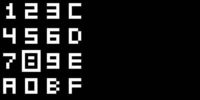
CHIP-8 fontset
This is the Chip 8 font set. Each number or character is 4 pixels wide and 5 pixel high.
unsigned char chip8_fontset[80] =
{
  0xF0, 0x90, 0x90, 0x90, 0xF0, // 0
  0x20, 0x60, 0x20, 0x20, 0x70, // 1
  0xF0, 0x10, 0xF0, 0x80, 0xF0, // 2
  0xF0, 0x10, 0xF0, 0x10, 0xF0, // 3
  0x90, 0x90, 0xF0, 0x10, 0x10, // 4
  0xF0, 0x80, 0xF0, 0x10, 0xF0, // 5
  0xF0, 0x80, 0xF0, 0x90, 0xF0, // 6
  0xF0, 0x10, 0x20, 0x40, 0x40, // 7
  0xF0, 0x90, 0xF0, 0x90, 0xF0, // 8
  0xF0, 0x90, 0xF0, 0x10, 0xF0, // 9
  0xF0, 0x90, 0xF0, 0x90, 0x90, // A
  0xE0, 0x90, 0xE0, 0x90, 0xE0, // B
  0xF0, 0x80, 0x80, 0x80, 0xF0, // C
  0xE0, 0x90, 0x90, 0x90, 0xE0, // D
  0xF0, 0x80, 0xF0, 0x80, 0xF0, // E
  0xF0, 0x80, 0xF0, 0x80, 0x80  // F
};
It might look just like an array of random numbers, but take a close look at the following:
DEC   HEX    BIN         RESULT    DEC   HEX    BIN         RESULT
240   0xF0   1111 0000    ****     240   0xF0   1111 0000    ****
144   0x90   1001 0000    *  *      16   0x10   0001 0000       *
144   0x90   1001 0000    *  *      32   0x20   0010 0000      *
144   0x90   1001 0000    *  *      64   0x40   0100 0000     *
240   0xF0   1111 0000    ****      64   0x40   0100 0000     *
Look at the left example were we are drawing the number 0. As you can see it see it consists out of 5 values. Of every value, we use the binary representation to draw. Note that only the first four bits (nibble) are used for drawing a number or character.
Conclusion
Hopefully this guide provided you enough information to get you started with your own emulator project. At least you should now have a basic understanding of how emulation works and perhaps a better understanding of how a CPU executes opcodes.
I have included my own implementation of a Chip 8 interpreter below which you can use as a reference. The zip file contains a binary for Windows but also includes the full source code of the emulator. Because the full source code is supplied, I recommend only looking at chip8.cpp file as a last resort to see how I implemented a particular opcode. The file chip8.h and main.cpp should be safe to view without spoiling too much. Actually, main.cpp mostly contains GLUT code which you can reuse in other (non-emulator related) projects as well.
- myChip8 - Latest (Windows binary + Source code)
- Early version of myChip8 from 2003 (contains a nice debugger)
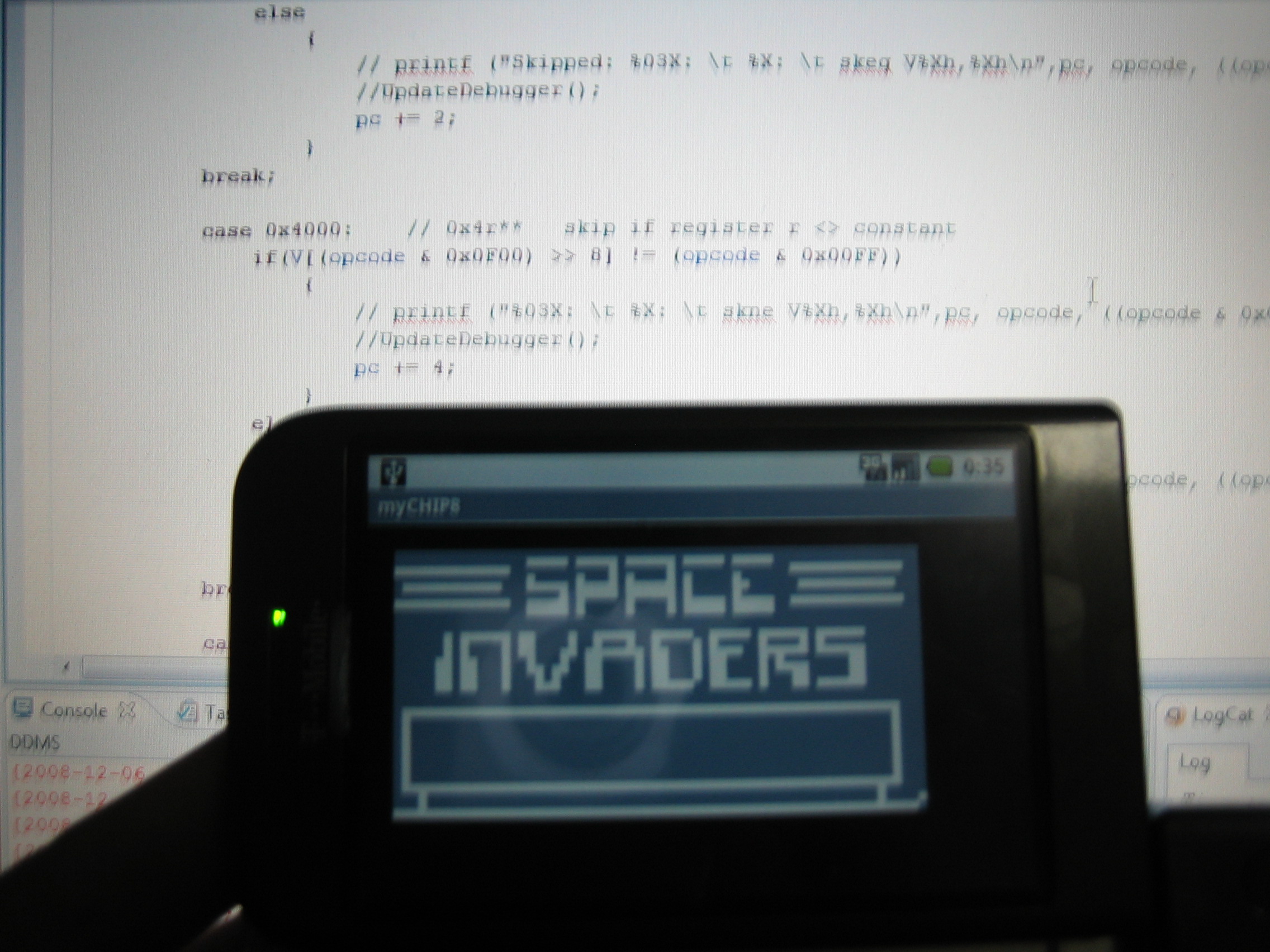
- An Android port I did in 2008
Let me know if you find this guide useful! If you have questions or think that essential parts are missing, please use the comment section 🙂 !
Credits
Special thanks to the following persons (many only known by their pseudonym) who have helped me greatly with my own emulation projects in the past and present.
- ector & F|RES (Dolphin-emu team)
- Saqib, zenogais, Absolute0, Shadow, gigaherz, Florin, Goldfinger (PCSX2 team)
- drk||Raziel & ZeZu (nullDC team)
- Hacktarux (Mupen64)
- Muad (nSX2)
- pSXAuthor (pSX)
- Shadowprince, Linker, Aprentice, SculleatR, ShizZy, Dave2001
Suggestions
After you have completed your first Chip 8 emulator, you might want to try one of the following things:
- Add Super CHIP-8 Opcodes
- Use function pointers instead of a giant switch statement
- Improve graphics by adding filters (Hqx)
- Port it to other platforms (Mobile?) or languages
- Move on to a more complex project for example emulating a Gameboy (Z80 processor)
Resources
- CHIP-8 on Wikipedia - System information
- Cowgod’s Chip-8 Technical Reference v1.0 - Recommended
- Chip8 tutorial - Goldroad.co.uk (mirror)
- (S)Chip 8 instruction set - Goldroad.co.uk (mirror)
- David Winter’s CHIP-8 emulation page - Contains some games
- (S)CHIP-8 instruction set overview - (Erik Bryntse)
- Chip8 emulator topic on Emutalk
- Chip8 emulator topic on NGemu
Advanced emulator resources
- Zilmar’s Emubook
- Zenogais Emulation Tutorials - (Offline, but available through Archive.org)
- Zenogais’ Emulation Tutorials - (mirror)
- Dynamic Recompiler - (mirror)
- Array of Function Pointers - (mirror)
- Introduction to Emulation Part 1 - (mirror)
- Introduction to Emulation Part 2 - (mirror)
- Laying the Ground For An Emulator - (mirror)
- Zenogais’ Emulation Tutorials - (mirror)
63 responses
Hello, First off, great job on the tutorial! I’m really enjoying the process of making my first emulator! I’m a CS major, and I don’t have a lot of engineering, low-level background. I’m following your guide using the Java programming language. I’m a little bit confused on something in the tutorial thus far. In the ‘Fetch Opcode’ section of the tutorial, you use a shift to left of 8 bits to add 8 zeroes to the end of the number. However, in every article on bitwise operations I can find, shifts didn’t add more digits onto the end of a number, they simply move their position. I did some experimenting and found that shifts do indeed add digits to the end, but I’m still confused on why exactly the shift is adding more digits. Thanks!
Hi Nate, thanks! Glad to hear you have a Java emulator coming along! About your question, let me try to explain what is happening there. You will have to remember that each opcode is 2 bytes long and that we use the data type unsigned short to store this value. Since we store all our data as bytes in the memory, this means we need to find a way to convert two separate bytes into unsigned shorts (2 bytes long) to get the full opcode. The first step is to retrieve the first byte from the memory and store it in an unsigned short (0xA2 -> 0x00A2). The 0x00 part is just holding 8 bits with the value of zero. Now if we are going to shift bits in an unsigned short, the total number of bits we are managing is always 16. You cannot add or remove any bits. When you are shifting an unsigned short one step to the left, it means that each bit gets moved one place to the left. During this step, the 1st bit will be assigned with the value of the 2nd bit. The original value of the 1st bit however is lost. The 16th bit does not have a neighboring bit on the right side. Therefor this bit will always be assigned the value zero. Now if we shift to the right side, the opposite happens. The 1st bit will be assigned zero (no left neighbor!) and the 16th bit will be assigned with the original value of the 15th bit. The value of the 16th bit is lost. Hope this helps you out a bit!
Laurence, Thanks for the explanation on that. That really helped out a lot. I have another question for you. Java doesn’t support unsigned types, and I’ve already encountered a few problems with that. I’ve since changed the data type for my opcode variable to an int. The only other thing I can think of that might be a problem in the future is my I (index) register. Does that value ever get bigger than plus or minus 32768 (or 0x8000)? NOTE: That number is the max value for the Java short data type. Also, I’m not sure how familiar you are with Java, but if you have another solution in mind that would be better than mine, please let me know! I’m all ears. :) Thanks again, Nate
Hey Nate, Glad it helped :). Actually I was having the same issues when I was porting my Chip8 emu to Android (Java). I’m not sure how I solved it (or if I even solved it at all). I found this website that might be useful for you: http://www.javamex.com/java_equivalents/unsigned.shtml
Hello Laurence, I’m from Colombia, I’ve been waiting for this tutorial a long time, I’m very happy to find this, and it’s very good explained, thank you for this.
Hi Falcon ^^ Man I remember using your PAD plugins on various emulators long time ago, when I was a kid. Thanks for this, I’m a translator for Dolphin emulator and now I’m trying to improve my C++ and emulation knowledge so this helps me a lot! Good to see you are still there, I really miss your plugins on Dolphin emu, the only ones that ever had a picture of the controller ^^
Super mario bros 3 was for NES, not SNES. You probably used NESticle. :)
Well you’re correct that SMB3 was available for the NES, but I think I was using Super Mario Allstars on the SNES! I did used NESticle for duck hunt :P!
Do i need to use opengl to draw on screen,or how else i could do it?
This example uses OpenGL, but on windows you could use DirectDraw or Direct3D
Hi dude love the tutorial my code is not complete i kinda skipped parts of the tutorial because i didn’t understand, Here is my code
Imports System.IO
Public Class Form1
Private Sub Form1_Load(ByVal sender As System.Object, ByVal e As System.EventArgs) Handles MyBase.Load Dim memory(4096) As Byte Dim V(16) As Char Dim I As String Dim pc As Integer Dim gfx As Bitmap = New Bitmap(My.Computer.FileSystem.SpecialDirectories.Desktop & "\test.png") Dim delay_timer As Char Dim sound_timer As Char Dim stack(16) As Short Dim sp As Short Dim opcode As String Dim key As Char Dim memoryPosition As Short
Dim openfiledialog As New OpenFileDialog openfiledialog.ShowDialog()
memory = System.IO.File.ReadAllBytes(openfiledialog.FileName)
While (1)
opcode = Hex(memory(pc)) & Hex(memory(pc + 1))

If opcode.StartsWith("A") Then
' Index Register Instruction
For b = 1 To opcode.Length - 1 I &= opcode(b) Next
End If
If opcode.StartsWith("D") Then
Dim x As Integer Dim y As Integer Dim height As Integer Dim width As Integer
x = CLng("&H" & opcode(1)) y = CLng("&H" & opcode(2))
height = CLng("&H" & opcode(3))
For b = 0 To height gfx.SetPixel(x, y, Color.Gray) PictureBox1.Image = gfx Next
For a = 0 To 16 gfx.SetPixel(x + a, y, Color.Gray) PictureBox1.Image = gfx Next
End If pc += 2 End While
End Sub End Class
This code will set pixels and thats it but it does not set them properly how can i fix this?
Hi Daniel, in your “D” opcode, a few things are missing. You need to reset V[F] to zero and set it when screen pixels are flipped. Also, your code doesn’t seem to copy data from the memory?
I have just begun coding one, I need some help, https://rapidshare.com/files/1098129696/Chip_8.rar
Hey Laurence. First off thanks for the great tutorial. I had a couple questions. I’m not new to programming but I am still a beginner (about 9 months of experience). I was wondering if you could elaborate on two things I’ve never done before: 1. How to read in the game files using fopen and 2. How to use one of the 3rd party libraries to handle the graphics. I realize the second one is asking a very big question, so perhaps just a link to a good and relevant tutorial would be nice. Good work and thanks in advance!
Hey Max,
Could you explain what kind of help you need?
Well, thank you for replying. I want to first finish my cpu core. I wanted some pixels drawing, I saw your code snippet, but all I saw was a white screen, and later black. But I think I have to finish the emu core first, right?
Its probably best to first implement all cpu instructions and see if your core can run properly (make it output all commands to the screen for example to see if it ends up in a deadlock). After that you can work on the drawing part (0xD000 instruction) which you can do by writing an array to a texture.
Thanks for your opinion. If you look at: http://forums.pcsx2.net/Thread-Emulator-Programming-Chip8-OPCODE-help?page=2 then the last post by me shows a problem, it has my source attached. Thanks.
I have been coding this in java to and so far have been using signed shorts for the opcodes. Will it still work even if it is signed?
It will probably work, you will just have to be careful when shifting bits left/right
Thanks alot I appreciate it oh and your BeatNode app looks pretty cool when I get some money I’m going to buy it!
Hey, I get unkown opcode 0xf090 and 0xf020, What should i do?
SOrry, problem was with CPU core.
Glad you figured it out :)
You’re welcome :)
Yup, I even got SDL graphics and keyboard input working, (I am just 15 :P)
I have begun implementing the opcodes and was wondering if this code looked alright as I was wondering how to implement NN and NNN: case 0x3XNN: for (int i = 0; i < 16; i++) { if (V[i] == 0x00FF) { pc = pc + 4; } else { pc = pc + 2; } } break; Would 0x00FF work for NN? Does NN have a specific place it should be stored at?
Hello Laurence Muller, I have a question about this SCHIP8 instruction: 00FB* Scroll display 4 pixels right. When it says “Scroll display 4 pixels right” does it mean shift the pixel in that direction by that amount without concerning the 4 pixels (now out of the screen) from the right, or does it mean to shift the screen right and the last 4 pixels to the right will now appear to the left?
Great writeup! I did a nearly line by line port to C# that runs the interpreter in a Windows Forms app. It’a running a little slow but I haven’t looked into any optimization and I believe that the multitude of type casting I’m doing on tick. It was great fun, thanks for the inspiration and the heavy lifting. http://www.dreambuildrepeat.com/Chip-8/Chip-8.zip
You says: “While this guide expects you to have some basic knowledge of computer systems and assumes you know a program language, it should also be an interesting read for people who are interested in emulation in general.” What do you mean by “Computer Systems”? Can you recommend any books?
Hey there, thanks for the awesome tutorial! After implementing all of the opcodes in C++ (that took a while!), it works fine! Optimized it a bit so it runs at full speed now, and instead of setting the redraw flag on the sprite draw opcode, I moved it to the 0x1NNN return opcode instead. It doesn’t “blink” anymore, obviously my gfx code wasn’t upto scratch, but it works fine: created my own little assembly game and ran it, played breakout, blinky…. Now its time to move onto NES emulation! Thanks, James.
Hi James, thanks for the feedback! Glad this guide could help you on your emulation journey. Good luck on your NES emulator!
I would personally create my own class to represent the necessary amount of bits. Using a signed short could be perfect in almost all cases, but it has to be perfect in ALL of them. Imagine something like overflow being intentional in the original game, the signed short give different behavior.
Hi James, thanks for this post, it is elaborately written and helps newbies and experienced developers just starting with emulation alike! One question I have is in regards to C++ templates and meta-programming. I have heard that op-codes can be generalized with templates and that it is a very elegant solution, but something that I would imagine requires a good amount of previous exposure to meta-programming and templates. I personally have a decent amount of C++ development under my belt, but the one area of C++ I haven’t used much is templates. Would you please recommend a way to accomplish this via pointing me in the right direction or showing a code sample that will help me get started? Thanks again!
I’m writing some 14 months after this post so I imagine you’ve got it sussed by now. But for others wo may stumble here: Use char datatype as it’s the only unsigned type and is 16bits. However for printing to sys.out…etc it has to be cast as an int or short otherwise the unicode character will be printed out. As for the byte type, always use a bitmask when assigning to another larger signed type variable and this cancels the compiler assigning the signed numeric value, oh and cast.. for example: char opcode = (char) ((byte1 & 0xFF) << 8 | (byte2 & 0xFF )); I was banging my head for a while about this and found the answer in Java Puzzlers by J Bloch.
I just wanted to share with you the solution to the BCD assignment for opcode FX33. If one doesn’t know how to use the modulus operator or if for instance it simply didn’t exist. Simple arithmetic basically. I’m substituting the variable names for memory[i] etc. for the names: hunds, tens, ones. hunds = VX / 100; tens = (VX - (hunds * 100)) / 10; ones = (VX - (hunds * 100 + tens * 10)); I do concede that it’s not quite as elegant as TJA’s solution. Anyway, Regards and Happy Coding :)
Thanks for your feedback Carlos! I’m sure this will help out other Java developers as well.
Hi. Thanks for the tutorial. It is very informative. I’m slightly confused about the skip if (not) equal instructions. One of the links that you gave on this page, Cowgod’s Chip-8 Technical Reference v1.0, http://devernay.free.fr/hacks/chip8/C8TECH10.HTM#3xkk says the following about the the skip if equal instruction: 3xkk - SE Vx, byte Skip next instruction if Vx = kk. The interpreter compares register Vx to kk, and if they are equal, increments the program counter by 2. The question that I have is shouldn’t it increment the program counter by 4 instead of by 2 since opcodes are 2 bytes and each program counter value corresponds to an single byte. If I increment the program counter by 2, then I will simply execute the next instruction, but If I increment it by 4 then I will skip the next instruction and execute the one that is needed. Any help is appreciated.
Thanks for porting it to C#, i’ve tried it out and it works great. i will learn lot’s from it.
Thanks for the tutorial, it confirmed that I already had a decent idea of how it all works. :P I’m think I’m going to give a C# implementation a whirl, should be fun. Anyways, I also wanted to let you know that your compiled example isn’t working correctly on Win7 x64, it does run, but, the games are all messed up, unless of course that’s what they’re supposed to be like? In pong, the board\paddles\etc, are drawn fine, but, you see the cpu playing at lighting speeds, it looks like several balls are moving around, or one is moving really fast. Tetris was just a big blob of pixels, like an “I” made of pixels, with some jittery non-sense happening at the top of the tower of pixels.. I don’t know, anyways, just wanted to let you know there were issues. :( Anyways, thanks again. :D
Thanks for the nice post. But I tested the binary you made available and it’s extremely fast. All games start and end (I die) in less than a second. It’s Win XP 32bits and the CPU is a core i5.
I am trying to write an emulator for Chip8 in Java using the LWJGL. How would I open the ROM? That is really the only thing I need help for. Thanks :)
That’s great, “Crckr Hckr”. Don’t stop here though, see what other emulators you can write. Perhaps the Master System, or maybe the NES would be an interesting project for you to take on?
Hi laurence.. Thank you for this EXCELLENT tutorial.. I hope you are still alive.
gfx[(x + xline + ((y + yline) * 64))] Hi, could someone please explain the above line? The 64 isn’t exactly obvious to me. Why do we need it there? I get that we’re trying to access our gfx array which represents our screen (2048 pixels?) but this statement isn’t making a lot of intuitive sense to me. Any help would be greatly appreciated. Oh and thank you for this wonderful tutorial!
I have also made my own Chip8/Superchip emulator, in Cubescript. It can only be run within the game Tesseract though :P I named it CubeChip for obvious reasons, you can catch the video here: https://www.youtube.com/watch?v=O9Opuf8GHPQ Your article is a nice introduction, but in reality some parts are misleading. If you’re still maintaining this article with updates it would be nicer to talk out of the comment section :)
Hello, I am sure you might have already received that kind of email, but I was on your CHIP_8 emulator tutorial and I came across a weird problem that I cannot solve Would you mind taking a look ? There is a makefile and everything to ease the test https://bitbucket.org/MrST4N/chip_8 Thank you very much, and by the way I found your article very interesting !
Yeah pretty much here as well, not sure I quite get the 64 meself.
Actually, take a look at this answer http://stackoverflow.com/questions/1730961/convert-a-2d-array-index-into-a-1d-index index = row * 4 + col (row is y coordinate, col is x coordinate, 4 is total number of columns) in other words: index = X + Y * NUM_COLS; in our case X == x + xline (original pixel x coordinate plus the current x offset) Y == y + yline (original pixel y coordinate plus the current y offset) NUM_COLS == SCREEN_WIDTH == 64 so: index = (x + xline) + (y + yline) * 64 Makes sense? :)
Hello, very cool tutorial, I have a question related to hexadecimals values. For example, the 0x0000 to 0xffff mask range. Where we get these values from?
Sorry that I entered sample text in all the fields, I can’t tell which is for email and name… Hi! This tutorial was great and I used it to start on my first Chip-8 emulator. I’m currently working on a full alphabetic implementation of the fontset (0-9, A-Z) but not done yet. I might be able to finish around tomorrow. Alphanumeric is about 0xB4 (probably missed some calculations) but all in all it fits quite snugly.
I had a question, If a single pixel on the screen is equivalent to 1 bit in the gfx array, then doesn’t that mean that the array should be 2048 bits in size? (256 bytes.) All the other emulators i’ve seen also use 2048 bytes (not bits) Why does this happen? I’m kinda confused
I had a question, If the graphics is bit-for-bit (if it’s a 1, draw a pixel) then why is the graphics memory 2048 bytes? Shouldn’t it be 2048 bits? (256 bytes) Most emulators also use an unsigned char array, so I’m really confused
Hi Laurence, thanks for this awesome article. I am in the process of making chip8 emulator in Java. I am making use of Java2d in place of OpenGL. I am getting some output, I think the that the game is moving too fast and so I am not able to make in sense out of the output. I am not sure about how much delay I should add after each render.
Thank you for your article helped write an emulator and a compiler for Android, you can find it here https://play.google.com/store/apps/details?id=com.corax.chip8ide
Looks great!
Hello there, I have a question regarding the fontset location in memory. Why is the fontset written in memory from 0x00 to 0x50, and not from 0x50 to 0xA0? I searched the web and found that 0x50 to 0xA0 is the space for built-in fontset. best wishes!
Are you sure that you display opcode is correctly implemented? Take for example the rom from here (but I think it can be reproduced with you provided rom ‘pong2.c8’ as well): https://github.com/badlogic/chip8/blob/master/roms/pong.rom A valid opcode is ‘DAB6’. Lets assume V[B] = 0x1e (decimal 30) This actually overflows you gfx buffer since it starts at y = 30 until y = 35. But as you know your screen just has 32 rows. I think it doesn’t crash because its a C++ program and that the memory after gfx is still unused. However, take the C# implementation from Patrick and you will see that Pong will crash as soon as you press 2 on the keyboard and the left “Pong-Bar” reaches the top of the screen. But you can also notice it visually in your implementation because the “Pong-Bars” do not break correctly when they are overflowing the screen. To fix this, write the inner loop as: for (byte xline = 0; xline > xline)) != 0) // if sprite pixel is set { byte posX = (byte) ((x + xline) % WIDTH); byte posY = (byte)((y + yline) % HEIGHT); ushort posPixel = (ushort) (posX + ((posY) * 64)); if (gfx[posPixel] == 1) V[0xF] = 1; // set vf register gfx[posPixel] ^= 1; } }
Hello, I’d like some clarification on a section. “ Before running the first emulation cycle, you will need to prepare your system state. Start clearing the memory and resetting the registers to zero. While the Chip 8 doesn’t really have a BIOS or firmware, it does have a basic fontset stored in the memory. This fontset should be loaded in memory location 0x50 == 80 and onwards. More details about how the fontset works can be found at the end of this guide. Another important thing to remember is that the system expects the application to be loaded at memory location 0x200. This means that your program counter should also be set to this location.” In the example you give for loading the fontset, you don’t offset memory[] by 80. However, in the example for loading the game, you do. What’s with that?
Hi. I wondered the same thing. There is an inconsistency since the tutorial even says that the fontset should be loaded at memory location 0x50 and forward, but then in the sample code below loads it from 0x00. (Please fix, Laurence) Both implementations seem to work since the memory space up to 0x200 is unused in the interpreter. It is easily fixable, what matters is that CPU instruction FX29 reads from the correct location. Otherwise this guide was very good. I had a lot of fun with this little project.
Sprites should wrap around, so: gfx[x + xline + ((y + yline) * 64)] ^= 1; doesn’t work if the sprite position > 64*32 - 8 part of the sprite would be outside of the array changing data from other variables (the stack in my case) gfx[(x + xline + ((y + yline) * 64)) % (64 * 32)] ^= 1; Works
Question, the article says to decode the first 4 bits of the OPCode but only uses the last 4 bits of it. why are the terms switched? 0xF0 means the last 4 bits are 1111 as it represents (end> 11110000 00001111 <start),.