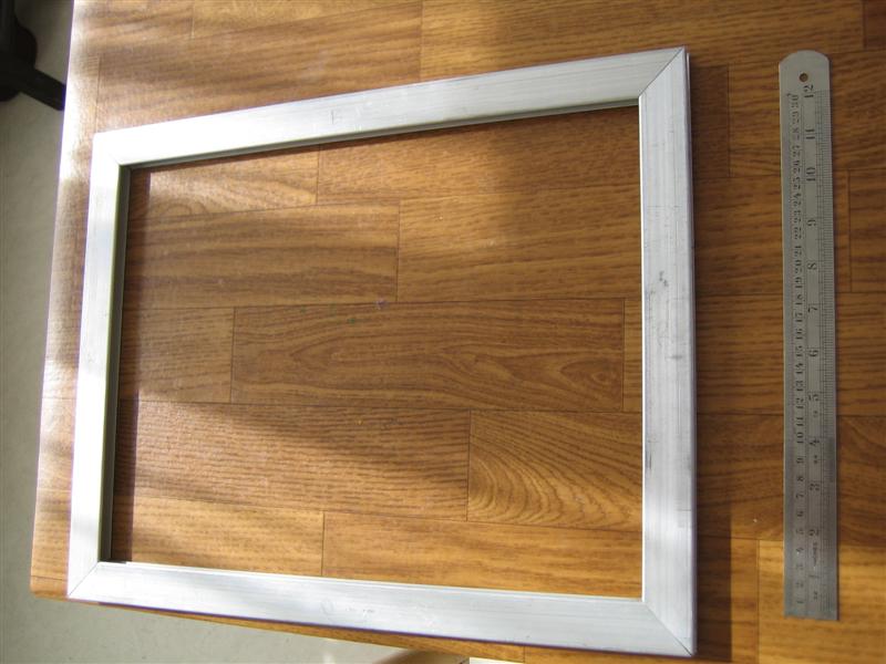
Inspired by other FTIR prototypes I decided to use an aluminum frame. The main reasons for are because its cheap and strong.
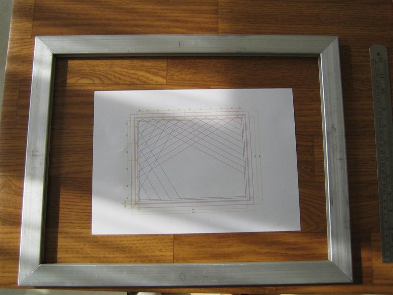
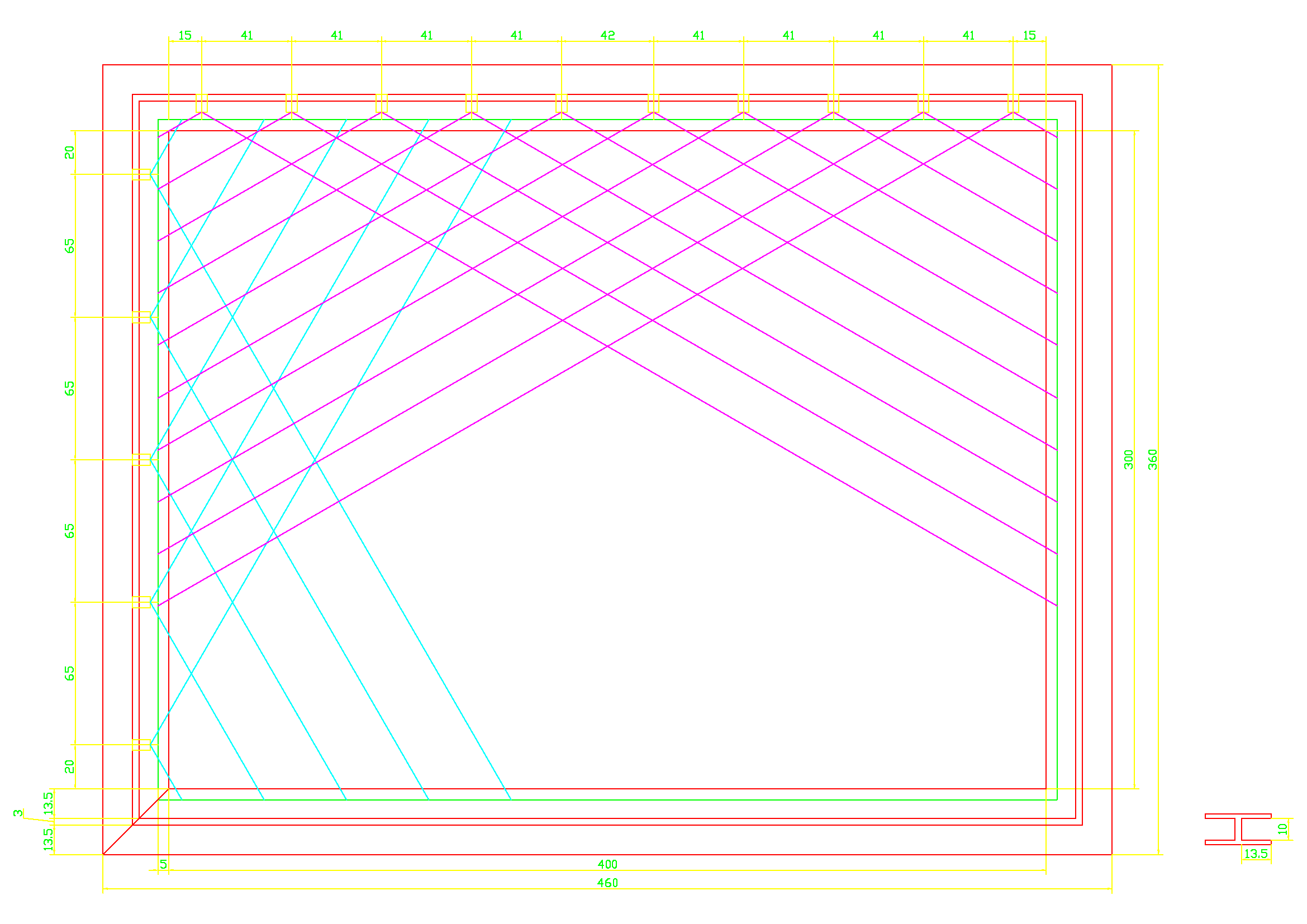
Before actually working on the frame, I made a drawing in AutoCAD. Within this drawing I could easily calculate the amount of IR LED’s I would need and at the same time see how the IR light beams would spread.
The local tool shop was friendly enough to cut the aluminum frame (H shaped) into the sizes of my drawing.
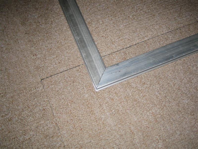
So at home I just needed to remove the edges in 45 degrees.
Needed equipment:
– Saw (for aluminum/iron)
– Mitre Block
– Clamp
– Workbench
– Drill
– Drill bits (multiple sizes)
– Punch
– Hand-file
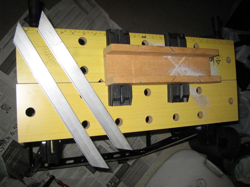
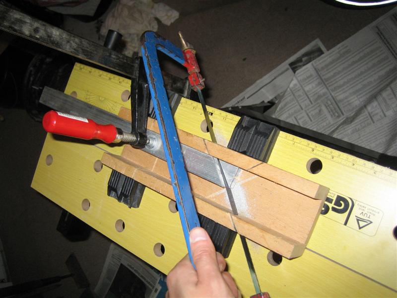
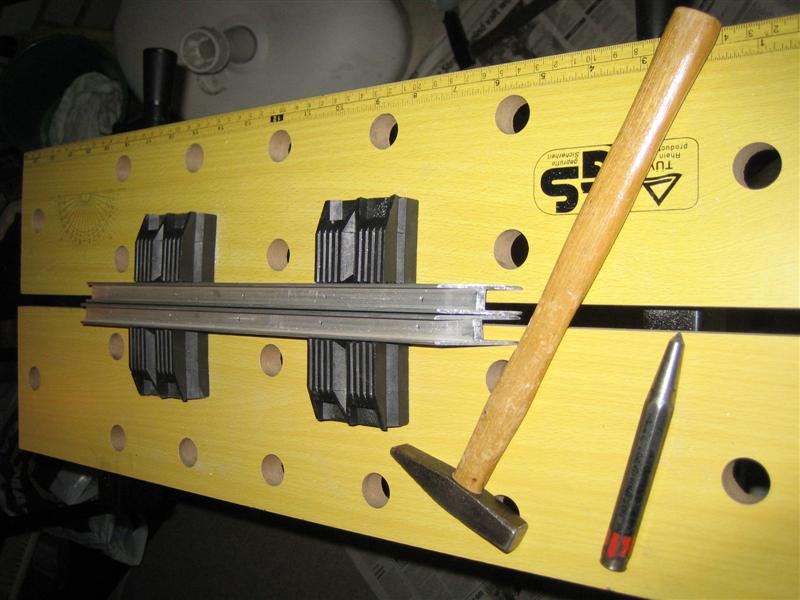
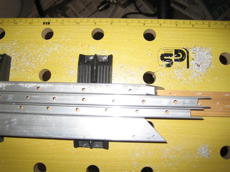
First I mounted the aluminum frame in a Mitre Block. To prevent it from moving during sawing, I used a clamp.
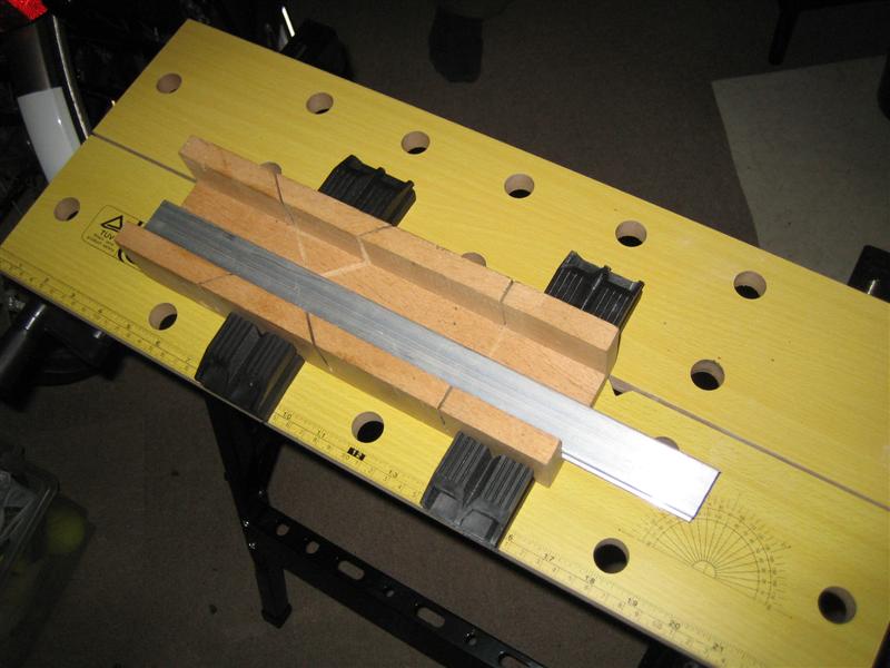
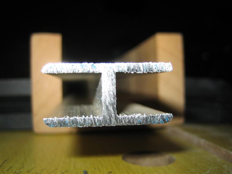
After sawing, I used a Hand-file to smoothen the edges. It fits nice:
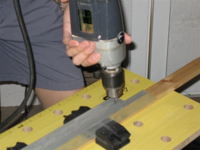
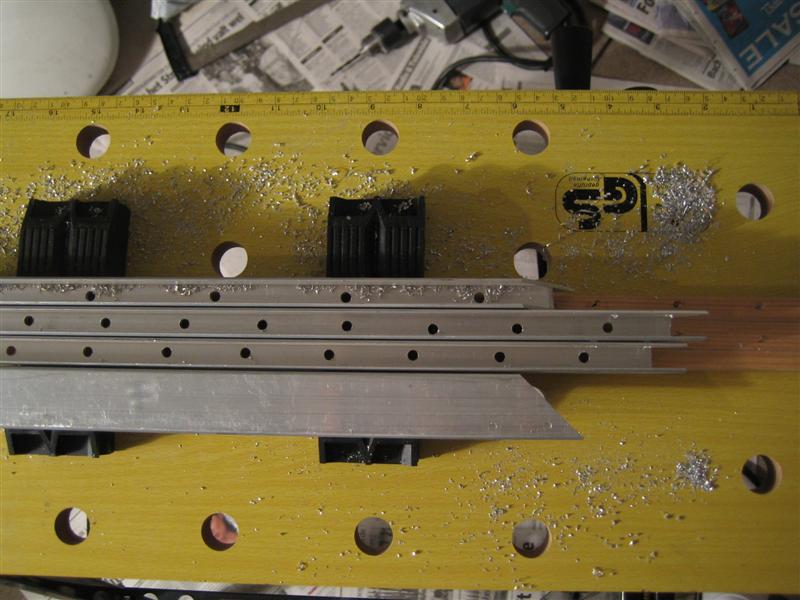
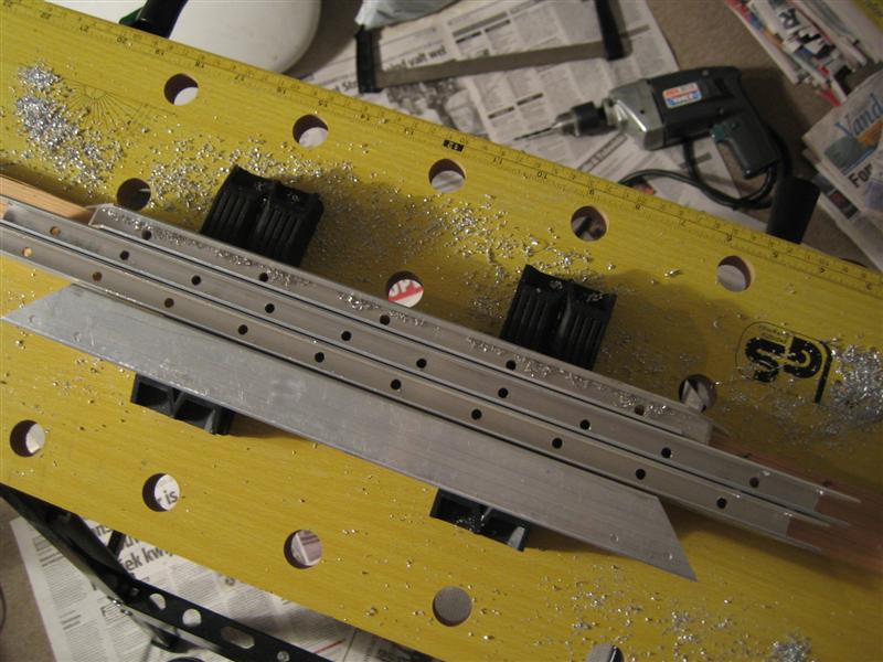
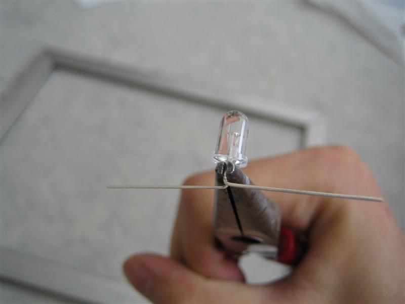
Next step is drilling holes for the LED’s. Before drilling I used a Punch to make sure the Drill won’t shift during drilling.You could start with a small Drill bit but I just started with 3.5 mm and after that I used 5 mm (which is the size of my LED’s).
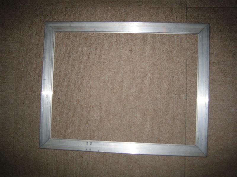
Almost done…
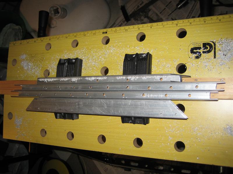
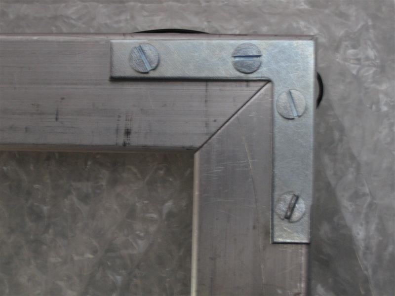
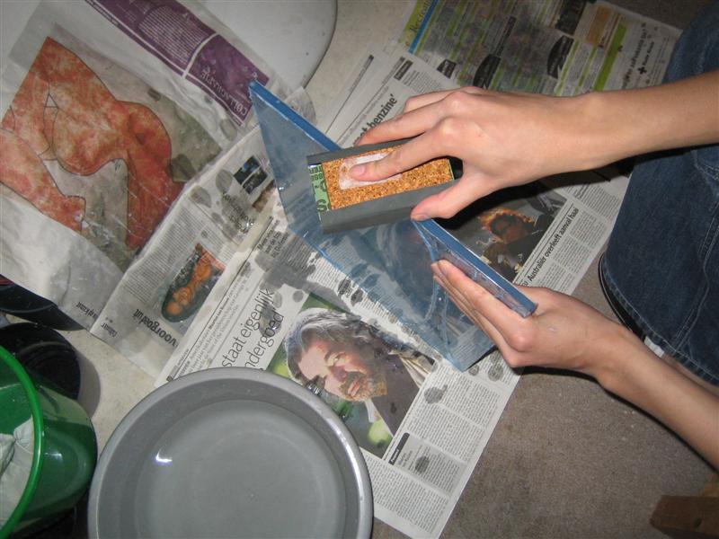
To keep the parts into place I used a construction like this:
Next time I’ll cover soldering the LED’s…
2 responses
hello, in the drawing you made, doesn’t it need to be symmetrically divided (the LEDs) Thanks!
Hello John! Wow, this is a really cool and interesting read! I was wondering why the leds are drawn to emit light at an angle like your CAD-drawing shows? Also, are the light emitted by the leds what reflects on your fingers and hence causes infra-red light to be emitted when it bounces off your hand? (the hand changing the wavelength of the photons…) It would be awesome if you could reply to my e-mail :). Henrik