In this final step of building the FTIR prototype I will cover the soldering of LEDs.
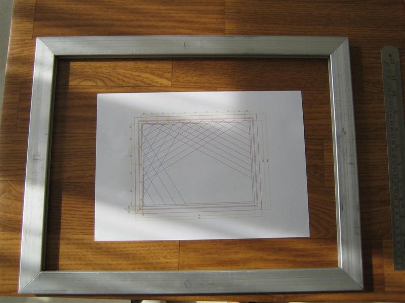
In my previous blog post I already calculated that 30 LED’s would be enough to cover the entire plate.
As power source for my LED’s I will be using a 12V DC Adapter (1000 mA).
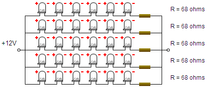
To calculate the LED array and the amount of needed resistors I used an internet tool the LED Wizard.
According to the wizard I should create 5 array’s of LED’s. Each array should contain 6 LED’s and one resistor of 68 ohms.
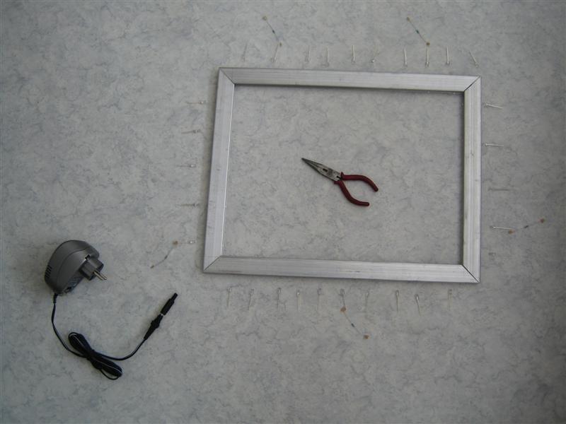
Needed equipment:
– Workbench
– Soldering iron
– Solder
– Wires and resistors
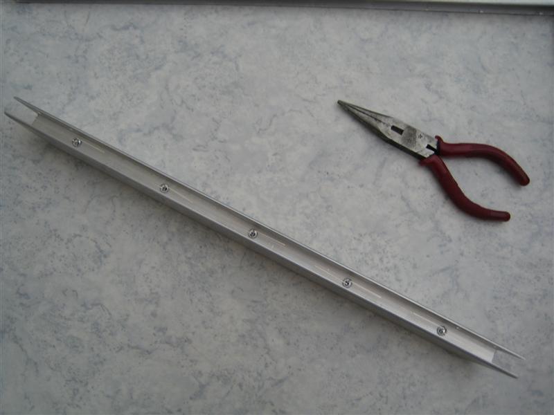
– Needle-nose pliers
– A steady hand
– Toilet paper!
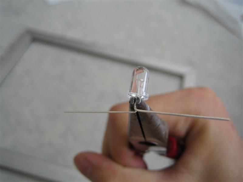
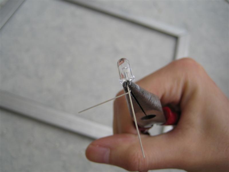
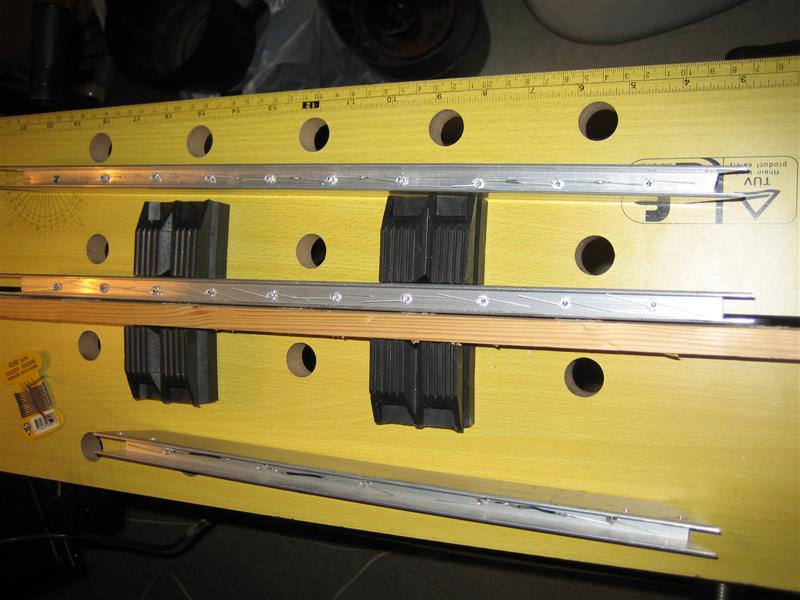
Bending!
First you should bend the legs of the IR LED’s. I would recommend using Needle-nose pliers to prevent breaking a leg. Also don’t bend it more than once.

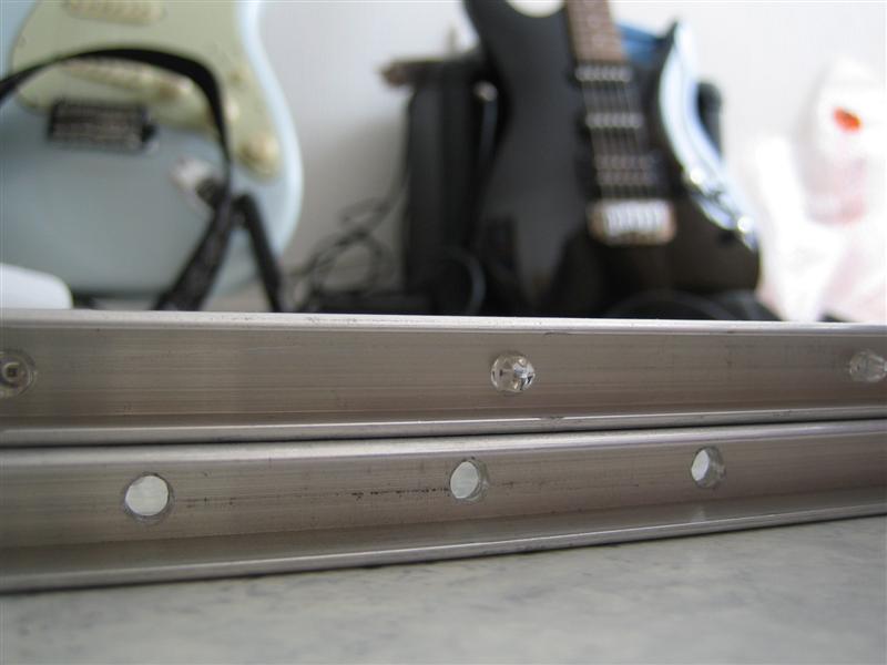
Be sure to check the holes you drilled, you really don’t want to get them stuck in there. To prevent the LED’s from being damaged, you should make them a bit larger than the diameter of your LED.
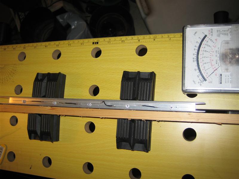
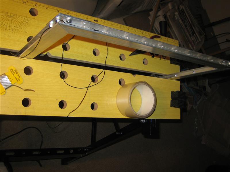
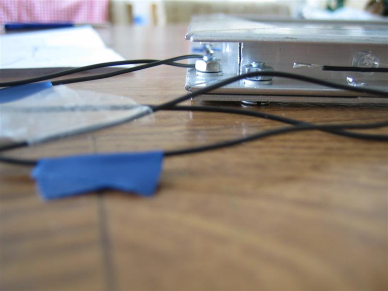
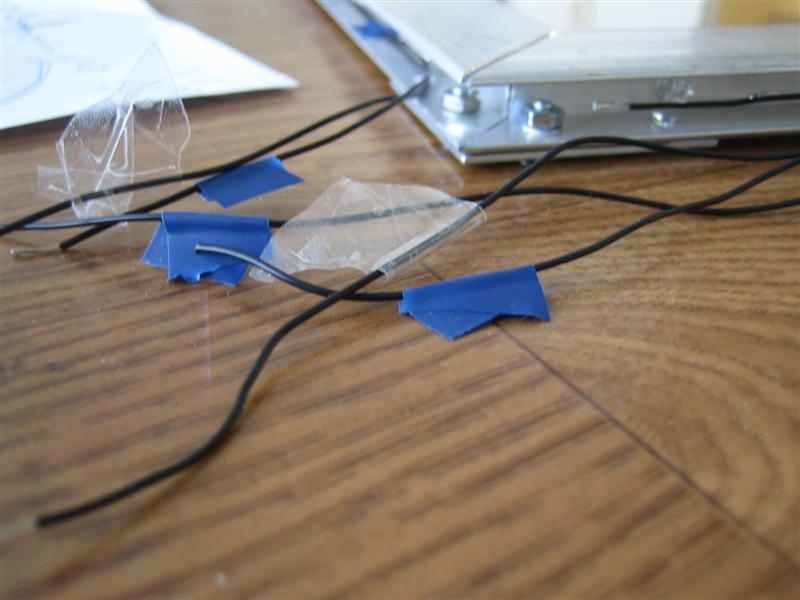
Soldering
Well I didn’t made much photo’s during soldering. But some general hints, don’t heat the legs of the IR LED’s too long because you probably end up melting the LED. Also whenever possible you should try soldering on some plate instead of what I did… soldering inside the small frame. However it makes it twice as challenging though :P.
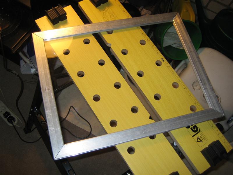
After soldering 3 sides, it’s time to put in the acrylic plate. You might want to use some toilet paper to keep the acrylic plate centered (The acrylic plate should not be touching the LED’s). Now closed the frame and continue soldering!
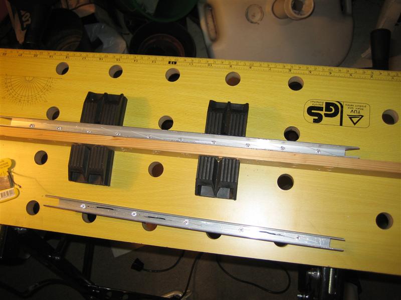
Almost done, just need to attach the power plug…
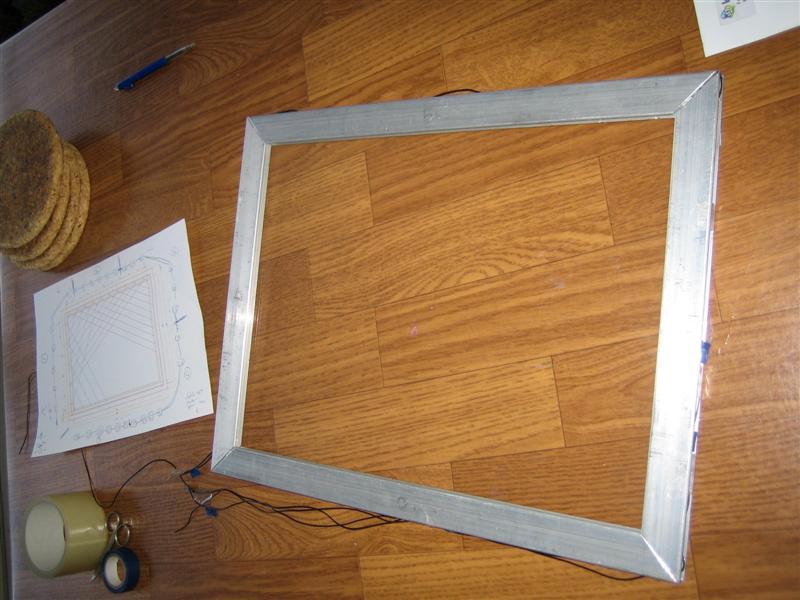
A new FTIR screen born…
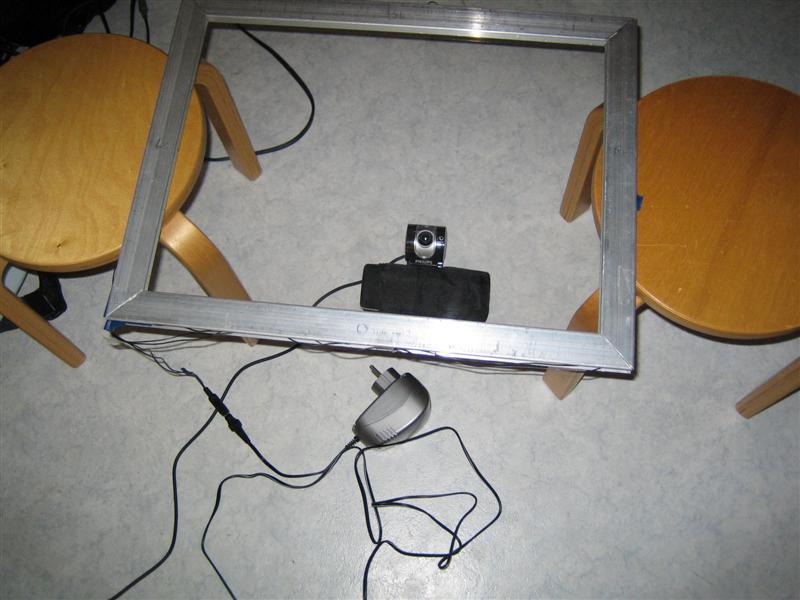
Coming up: First tests on the FTIR screen…
7 responses
Hi man! This is a really interesting project. I’m from argentina, and this blog inpulse me to make my own ;). These weekend I was making some tests, just with some IR leds, a glass that I found in my home and a Genius VideoCam NB, I’ve to tell you that was really easy to remove the IR filter from this cam. I download the touchlib, touchTracer and all it’s dependencies from they source, and compiled all. I found some problems here, because I download all of the last versions of the dependencies, but at last all works just fine… The result of the test with the leds, glass and cam, wasn’t too much great, because was all on the fly, but the touchlib and touchTracer recognized some movements :D I’ve to say that I’ve not to much knowgement about electronics…, and that I’m was searching a lot about making the arrays of the leds, and trying to understand why if you connect a led directly to the power, it just burn… :P , I was trying to get the same wiring diagram solution that you but it gives me other things…, the closest one was the same array but with resistors of 1ohms. Can you say me the specifications of the leds that you used? The ones that I buy came without specifications, so I had to assume they… Today I’ll start the project again, buying all the necessary things, and I’ll try to make it good, step by step. So, wish me luck!!!
Hi, are those Osram SFH485 leds?
@Vilen: No, these are low cost no brand 880nm IR LEDs.
Hi there, Can i check with you what are the specs of the kind of black wires you used to connect the circuit up? I totally know nuts about electronics
@George: Heya, nothing special, just normal copper wires. You can get them at any electronics store.
Hi, thanks for the help. I found a website that sells IR LED but there are like so many specs that goes with it. What are the specs u used for your LED? Wavelength is 880nm What about the power dissipation, current foward IF, Voltage VF max and lastly angle viewing? Sorry for this long question. Appreciate your help
HI, i have several questions to ask. 1) how to connect the led to the dc power? 2) How do you place the acrylic plate probably? 3) Can u take a picture of the side of the FTIR screen. Like the place u put led. i wanna use it for reference.